MEA–03 / BORG Lab · Summer 2026
Microwell insert and microelectrode layouts
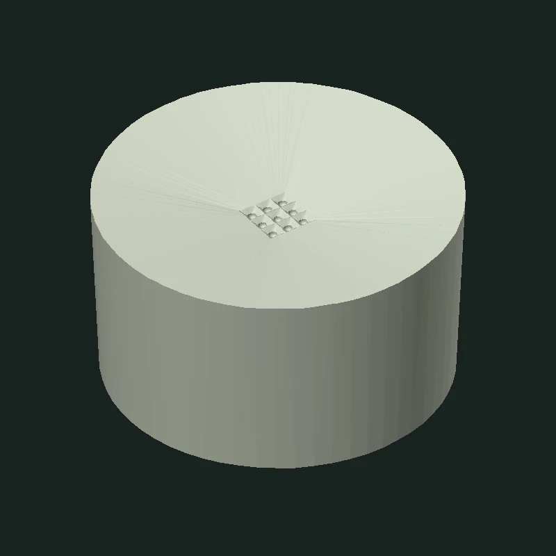
I independently designed and resin-printed a removable insert for the lab’s existing well plate. I also drew nine alternative microelectrode layouts in KLayout to explore how the electrode pattern could change for different target neurosphere sizes.
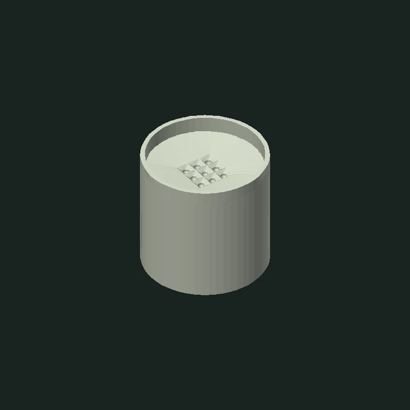
The insert sits inside a larger culture well. Its smaller microwells are intended to position microelectrodes close to the cultured neurospheres. My mechanical work focused on making the insert fit the plate while keeping it easy to place and remove.
- KLayout
- CAD
- Resin 3D printing
Design, print, and refine the fit
Designing for the existing well plate
The lab gave me the dimensions of the target plate and an approximate height for the smaller wells. I used the plate dimensions to set the outer geometry in CAD and the target height to position the smaller wells. Raising their floor reduced the distance the electrode device would need to reach.
What changed after the first print
The first resin print fit too tightly in the actual well. I reduced the insert’s outer dimensions and added a lip around the top to make it easier to handle. The second print fit the target well plate. Testing in the plate made the fit problem clear and gave me a concrete change to make before printing again.
Printing the part directly
I initially considered making a mold and casting the insert. Printing in resin let me produce the part directly and check its fit without first making a mold.
CAD / STL Compare the supplied meshes
STL Model 01
STL Model 02
Rotate either model to inspect its shape. Use the controls or pinch to zoom.
Model sources & scale notes STL
The STL files do not include units, and the available records do not confirm which file corresponds to each physical print. Both views start at a shared display scale, so compare their shapes rather than treating them as dimensionally accurate.
PHOTOGRAPHS Resin prints and fit
Electrode layout exploration
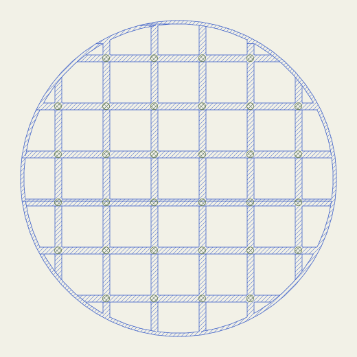
I varied two parameters in KLayout: target neurosphere diameter (250, 350, or 450 µm) and electrode marker size (10, 15, or 25 µm). Each drawing contains 32 electrode references. Comparing the drawings at a shared scale shows how the marker size and spacing change relative to the target neurosphere diameter.
The nine layouts are alternatives for different experimental requirements. The gallery pairs each drawing with its source dimensions and lets you inspect the geometry up close.
Source & extraction notes GDS → SVG
The file contains one TOP cell, three reusable electrode cells, and nine configuration labels. Each preview includes one local layer-1 polygon and its 32 layer-2 electrode references. All full-layout previews share a 520 × 520 µm frame; closeups share a 150 × 150 µm frame.
Each preview is centered at the same scale. The GDS uses 1 µm units with 1 nm coordinate precision. The colors distinguish the two numbered layers; they do not identify materials.
The previews omit polygons and paths outside the nine layout regions, including a large polygon on layer 0. The original GDS includes all of that geometry.
The 250 µm neurosphere / 25 µm electrode-marker configuration uses a 38 µm reference grid step; the other two 250 µm configurations use 40 µm. The GDS labels and reference positions agree.
Project outcome
I fabricated a resin insert and verified that it fit the target well plate. The nine electrode configurations remained layout designs. The project ended at fit testing for the insert and layout exploration for the electrodes, before fabrication or experimental testing of the arrays or combined recording system.